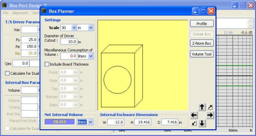
The solution is to use flares to allow higher airspeeds before turbulence sets in. For an unflared port, you need to stay below 10 m/sec whereas adding a 35mm flare to an 86mm port lifts the acceptable speed @30hz from 7 m/sec to around 22 m/sec. Pipe mode resonance. As the port gets longer, the resonant frequency of the port decreases. If the box design requires a bend or 'elbow' in the port, always measure down the 'middle' of the vent to determine the correct cut length. 'Rounding-Off' Slot Vents Some enclosure designs are based upon 'slot' vents. The inherent design of these vents utilize some of the enclosure walls as part of the vent length. The DD Box is more than just a style of box; it’s a scalable system that every DD subwoofer is designed to work with. We designed the DD Box to meet the needs of listeners desiring big bass that didn’t have the cargo room for a wall of subwoofers.The research that led to the development of the DD Box is at the core of our subwoofer design philosophy, and the outstanding performance of our. Apr 26, 2018 - Dual 6.5 Inch PORTED Subwoofer Box Design The volume of this box is 1 Cubic Feet and is tuned to 36 hertz Blueprints (only) – How to make (NOT the actual box) A PDF of the blueprint (box design) will be emailed in approximately 30 minutes after you order. How Much Time is Needed to Make a Subwoofer Box Design? Imagine how much time you will need to calculate the length of a port by its area and the net volume of a box, then calculate the occupied volume by the port, add it to the net internal volume of a box, and only after that, calculate the dimensions of a box, taking into account the material thickness.
Overview:
This is a calculator for designing a L-Slot Vent Bass Reflex Enclosure. The formulas used in the calculator create a design that suggests the most maximally flat response in an anechoic environment based on the number of drivers, the thiele small parameters and the allotted dimensions specified in the user’s input fields.
The calculator does NOT take into account the effects of placing the enclosure into the listening environment. This type of enclosure may not be the most suitable option for your application. I recommend reading the articles in the Projects category on box design for further information.
Feel free to check out the other calculators on the site as they may provide the results you are looking for. —> Enclosure Calculators You can also request a totally custom design for your driver(s)/application by filling out the form in the Blueprints Inquiry page.
The spreadsheet calculator loads via iframe below the diagrams. You can also access the spreadsheet here.
Instructions:
If you are just looking to downlaod WinISD and want to skip the overview, you can go directly to the last section of this page
Screenshots
The main interface...
Whilst you can only have one graph window open at a time, you can have multiple projects open. This makes it easy to compare different designs.
Working through each Tab on an individual project window
Clicking on the Parameters label toggles the visibilty of the bottom half of the panel(regardless of which Tab you are on)Box-port Design 2.2
 on the graphic will change the volume.
Note that the volume shown is the Working Volume,and does not include the space occupied by the driver or ports
Dragging horizontally will change the tuning frequency.
The graphs change as you go.Enter port details on this tab.Set the end correction from the drop-down list showing which ends are flanged**.
In a multi-port design, the vent length shown is for each port
This is also where you can see the frequency of the first port resonance.
Note**: Flanged means flush with a panel. Not to be confused with flared,which WinISD does not support. Once you have your design, you can useBoxnotes or Sonosub to account for flares as well as the volume occupied by the components.
 If using multiple drivers, this is the total power,not the individual power to each driver
Using the
 Save button usually pre-loads the file name into the save dialog box for you. (unlike choosing Save from the menu)
The three most commonly used graphs...
The most important one.Watch this as you change box size and tuning frequencyWinISD recommends keeping velocity to 17 m/sec.
This can be refined further by using Flare-itKeep your excursion to Xmax + 10%
High Pass Filter modelled in WinISD
WinISD has a built in filter section. Access it by selecting the EQ/Filter tab and click the Add button to get this screen. This allows you to model the effects of different filters.
To control cone excursion below the port tuning frequency, it is often neccessary to employ a high pass filter.
A favoured design is the Linkwitz-Riley filter 4th order filter, which is entered as follows:
The 4th order filter has a Q of 0.5 - if you enter any other value, WinISD will ignore it.
To achieve control of excursion without compromising SPL more than neccessary, try different values for the Cutoff frequency. Here is a graph showing how excursion changes with filter design frequency. Xmax is the thin red horizontal line at 9mm
In this example, the blue graph is the one which achieves a maximum excursion of Xmax + 10%
Modelling Boost
The effect of boost can be modelled with the Parametric EQ filter.
The first step is to specify the type of boost.
The software defaults to a Q of 2.0 which seems to be the best fit.
Other values may be more appropriate though - here is how SPL changes with different values for Q
The second step is to set the correct System input power.
WinISD takes whatever you set as the System Input Power and then adds the boost. The result of this process must not exceed the maximum power of your system.
This means that the System Input Power must be set lower than the maximum power by an amount equal to the boost.
The following table shows how much to reduce the power for a given boost
| Boost in dB | Divide maximum power by: |
| 1 | 1.3 |
| 2 | 1.6 |
| 3 | 2.0 |
| 4 | 2.5 |
| 5 | 3.1 |
| 6 | 4.0 |
| 7 | 5.0 |
| 8 | 6.3 |
| 9 | 7.9 |
| 10 | 10.0 |
As an example, the Blast Furnace is designed for 240w maximum power and has a boost of 6dB.
For 6dB, we must divide the maximum power by 4, so we set the System Input Power to 60w
As a check that you have got it correct, load a second copy of your project, remove the boost and set the System Input Power equal to your maximum power. Compare the SPL at the boost frequency for the two projects - they should be the same.
Here's our example continued. Red line is 240w with no boost. Green is 60w with 6dB boost @ 35hz. Notice how the two curves are equal at the boost frequency of 35hz
Signal Generator
A signal generator is also included for testing speakers via your sound card and has a range of control options including selecting the frequency from the cursor position on the response graph. If using this function, be careful not to overdrive the output The generator allows you to produce a single frequency, or a sweep across a range.
For the single frequency option, you can manualy specify the frequency, or you can use the cursor to pick the frequency from on of the WinISD graphs.
Unlike some other products, this one doesn't produce any clicks during sweep mode.
There is also an output attenuator, allowing control of the signal level
Recently I have used TrueRTA's spectrum analysis software to have a look at the signal WinISD produces.
TrueRTA has several price / performance options, with this handy oscilloscope function in the free version.
I discovered that the default attenuation of zero, leads to an overdriven situation - at least with my sound card and windows setup.
The following TrueRTA screenshot shows how the signal has the peaks clipped. This produces a whole stream of harmonics. Not the best signal for testing your speakers
The following TrueRTA screenshot shows the results of decreasing the output level from the WinISD tone generator. The clipping is gone and the output is a clean sine wave. Note the vertical scale has been changed from 2 to 1 volt / division
Setting the Attenuation control to 6 was enough to restore a pristine sine wave. Your results may vary
Now, whenever I use the tone generator, I use TrueRTA to make sure I'm not getting a clipped signal
Flanged vs flared ports
Some people get confused as to the difference between flanged ports and flared ports.
A flanged end is an end that terminates in a flat panel, such as the wall of an enclosure.
A flared end is one that has an expansion section, typically one quarter of a circle in cross-section, to control port noise.
WinISD can factor in flanged ends by applying an end-correction factor. The current version cannot handle flared ends.
Here are some examples...
Since WinISD does not know about flared ports, a manual correction needs to be done. As the following drawing shows, part of the air in a flared port belongs to outside the port. It is generally accepted that half the flare radius needs to be subtracted for each end that is flared. The effective length is what needs to be entered into WinISD.
Speaker Box Calculator
Help file and FAQ
The help file and FAQ has all you need to know in order to use the software. WinISD is freeware with a facility to make a donation.
Quick Tip: Entering driver parameters
Driver parameters can be a pain to enter into the database. If you're having trouble getting it to accept parameters, follow this advice from one of the authors....
Try entering just Qms, Re, Mms, Cms, Bl, Sd, hg, hc, Xlim (optional) and Pe. Do not change any parameters the program calculates. That way the data is consistent. You can of course add the dimensional parameters if you like
If you can't get that to work, user Soho54 from AVSforum swears by the following...
Enter the numbers in this order: Sd, Re, Le, Fs, Qes, Vas, Qms, xmax, and then Pe. That's it, now save
Case Study
A case study used to prototype the snorky design illustrates the use of WinISDAdditional WinISD resources
- Steve Dart's excellent tutorial on using WinISD including entering driver parameters without errors
- A few observations about the various graphs can be found in this discussion at Speakerplans.com
- There are quite a few subwoofer driver files at Hometheatershack
While you're here, you might want to check out some free software that compliments WinISD
Whilst WinISD is excellent for designing your working volume, tuning frequency and filter frequencies, there are some things it doesn't do. The following sofware adds plenty of value to your design process.
Box Port Design Download
Boxnotes - check your enclosure design for resonances, factor in the volume taken up by ports and print your cutting list
Sonosub - design a cylindrical subwoofer. Check resonances and clearances
Flare-it, - find the correct port diameter and flare size to avoid audible turbulence
Subsaver - calculator for finding component values for a 2nd-order high-pass filter
QRDude - Software for designing advanced QRD diffusers
You can download WinISD from Linearteam in Finland.
Box-port Design 2.2 Download
This overview describes version 0.50a7 Pro
There is a later version which has similar functionality ie it also calculates box volumes for ported and sealed enclosures using an easy to use interface and also calculates port lengths.
Many graphs are available, including the three used in the Projects section, ie Sound Pressure Level, Vent Air Velocity and Cone excursion, all relative to frequency.
An extensive database of drivers is included and it is easy to add your own entries. This lets you compare different drivers before you go out and spend any money. It is surprising how the final box size and response varies with the driver chosen. Bigger and dearer isn't always the best. Choose wisely, grasshopper!
Comments are closed.